shop/products.hot_products

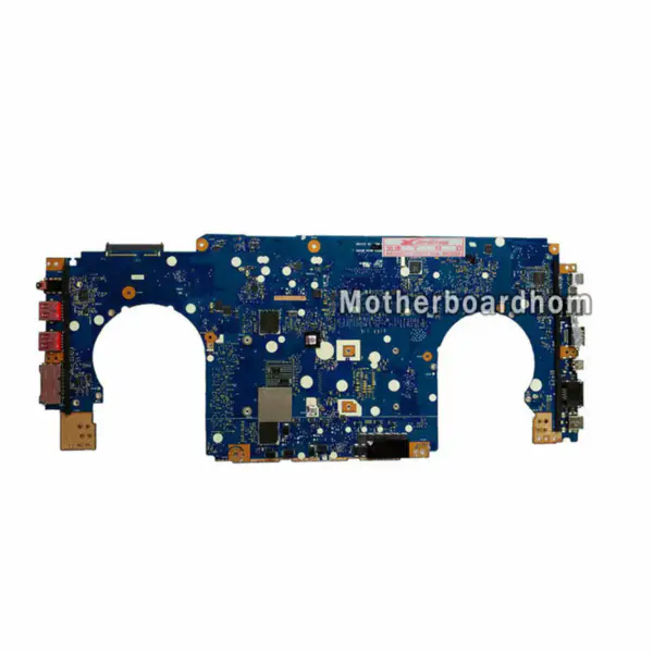
Asus GL502VS GL502VS motherboard
$302.00


Asus B85M-E hovedkort B85 LGA1150 Micro-ATX
$62.00
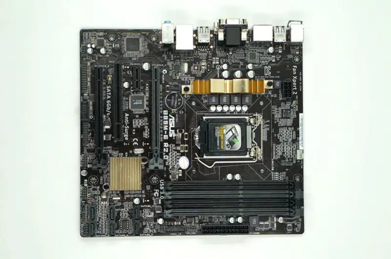
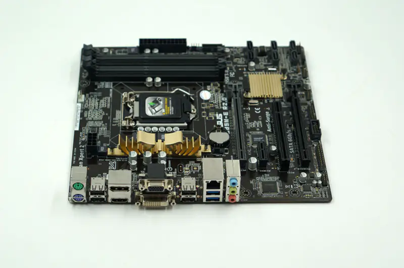
Asus B85M-E R2.0-hovedkort
$64.00
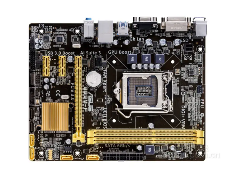
Asus B85M-F Desktop Motherboard B85 LGA 1150 i7 i5 i3 DDR3 16G SATA3 USB3.0 Micro-ATX
$43.00


Asus B85M-F PLUS B85 LGA 1150 Micro-ATX-hovedkort
$56.00